![]()
April 30, 2008
|
A trailer load of parts arrive in Muscle Shoals & is quickly unloaded:
2
pistons (April 2008) |
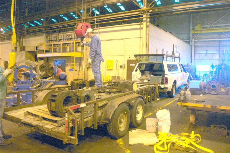 Photo: Bill Nash |
| Pistons being unloaded. Ronnie Jones looks on. |
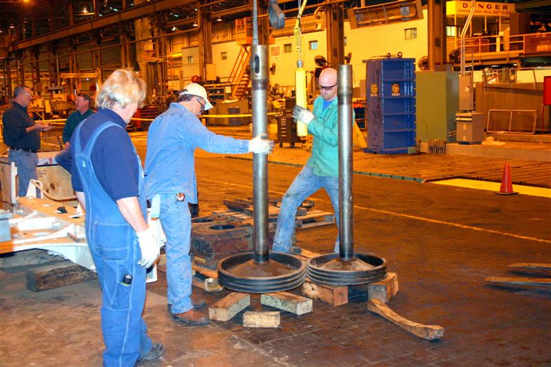 Photo: Bill Nash |
| Volunteers Bill Nash & John Mandell with 786 frame & delivered components |
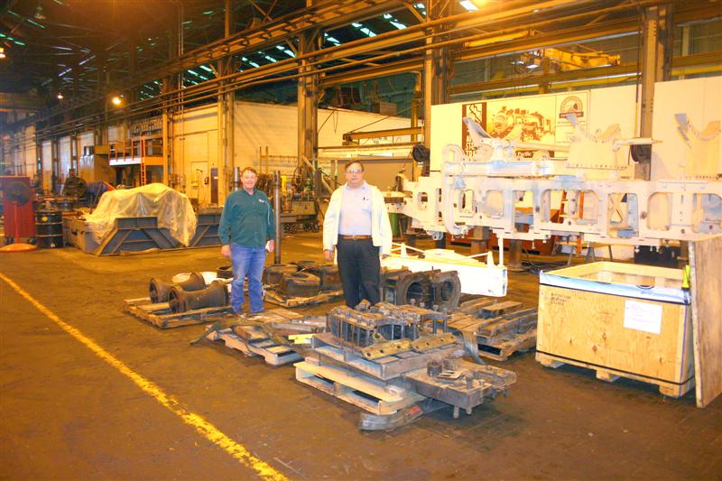 Photo: Bill Nash |
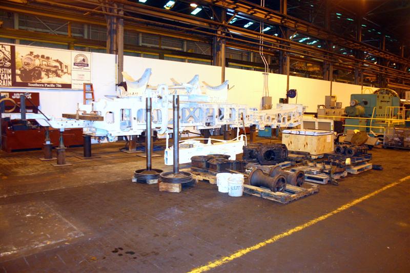 Photo: Bill Nash |
|
| Some driver boxes, before being cleaned. |
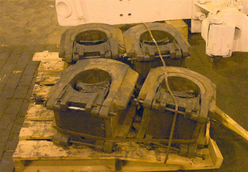 Photo: Bill Nash |
| Cages for the valves (4) were cast and initially machined for the side openings.. They are shown here with the insertion tools. They will be installed in the cylinder-saddle casting to the proper depth and then machined to the final inside diameter. |
 Photo: Bill Nash |
| Pistons/valves and crossheads being evaluated for condition. |
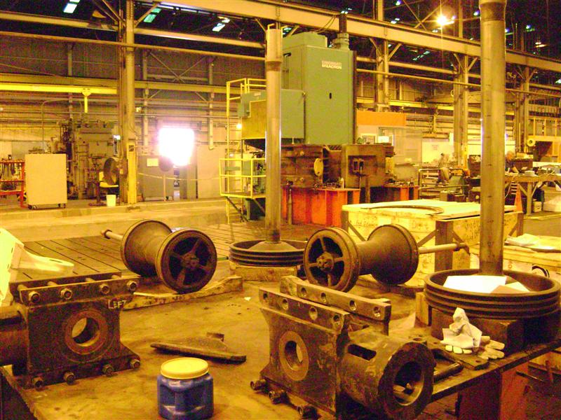 Photo: Steam Operations Corporation |
|
New cylinders, bolted together with taper bolts, mounted on the horizontal
boring mill. The current operation is to mill the underside of the cylinder assembly to fit the frame rails. This allows the cylinder to be mounted on the frame for various measurements. It will make numerous "round trips" between the frame and the milling machine. |
 Photo: Steam Operations Corporation |
| Another view of the cylinders, in position for machining the bottom mounting surfaces. |
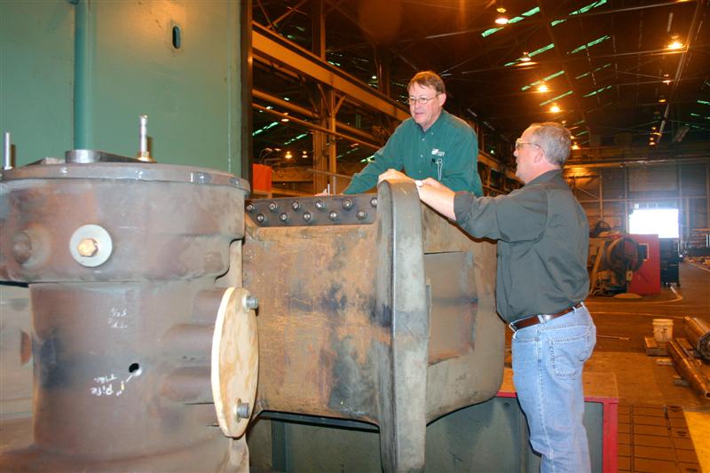 Photo: Bill Nash |
| Ronnie Jones is the principal machinist. He has also been working on the CAD drawings, adding detail as the operations progress. |
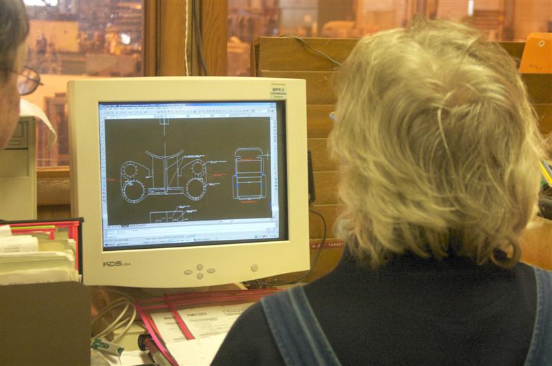 Photo: Bill Nash |
| This facing mill (cutting tool) will be used to create a large flat surface. |
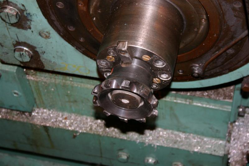 Photo: Bill Nash |
| Machining frame fit on cylinder bottom |
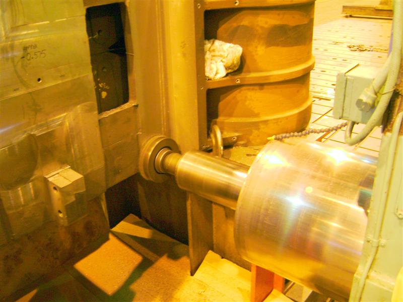 Photo: Steam Operations Corporation |
 Photo: Steam Operations Corporation |
|
| Machinist Ed Pettus is cutting surfaces to mate to the sides of the frame rails. |
 Photo: Steam Operations Corporation |
| This end mill (cutting tool) is being used to accurately machine the lower sides of the cylinder to precisely match the outside width of the frame rails. |
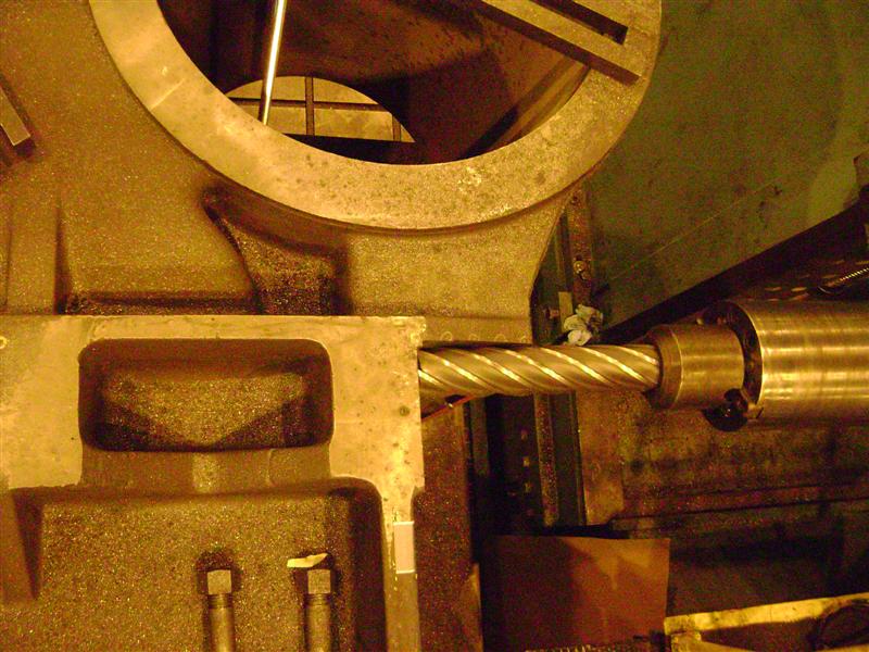 Photo: Steam Operations Corporation |
| Another view of the frame rail sides being machined. |
 Photo: Steam Operations Corporation |
|
This dial test indicator is used to accurately align the axes of the
cylinder with the boring mill or to "pick up" the precise location of some
feature. Here, the dial is indicating the center line established by a pin to lay out, drill and tap holes for engine truck fulcrum and bottom covers. |
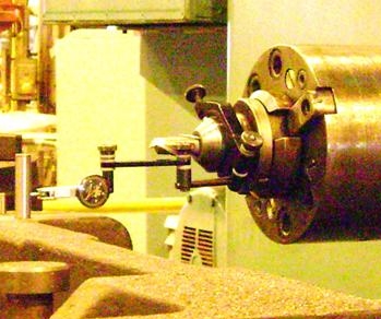 Photo: Steam Operations Corporation |
| Another indicating step |
 Photo: Steam Operations Corporation |
| Machining bottom center on location for application of the engine truck fulcrum bracket. |
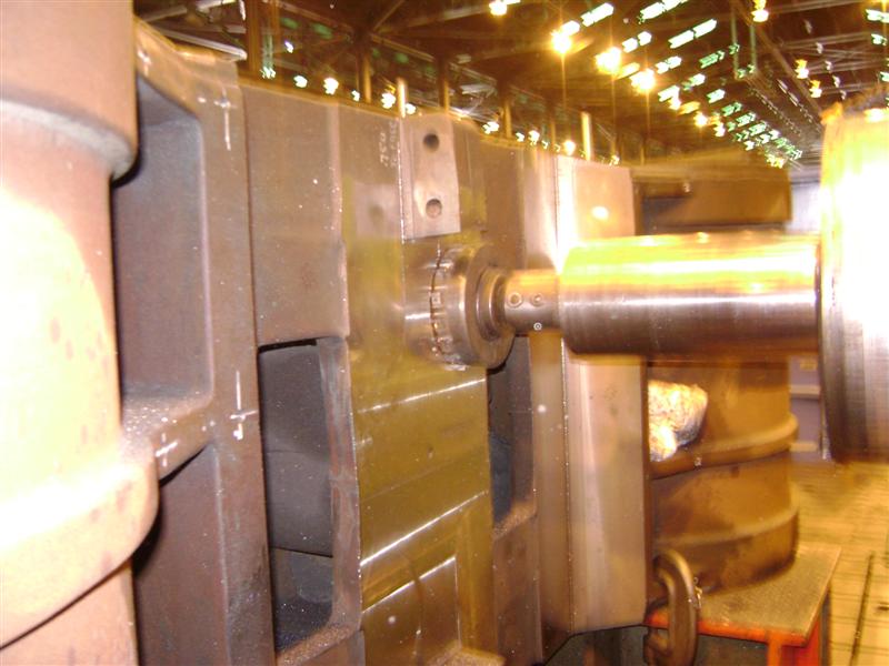 Photo: Steam Operations Corporation |
| layout for engine truck spring equalizer fulcrum bracket |
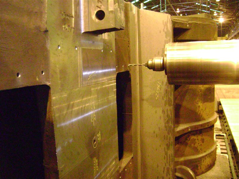 Photo: Steam Operations Corporation |
| Ed Pettus cutting 1/4 inch radius between vertical and horizontal machined surfaces. |
 Photo: Steam Operations Corporation |
| Machining of cylinder bottom to fit the frame rails is complete. |
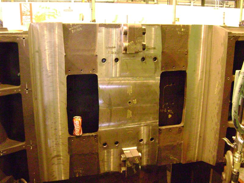 Photo: Steam Operations Corporation |
|
With the bottom of the cylinder assembly complete, it
can be installed on the frame for measurement or put on this holding fixture
for further machining operation. Scott Lindsay (Steam Operations Corporation) and volunteer John Mandell looking over the holding fixture. |
 Photo: Bill Nash |
| Original cylinder assembly with lots of notes and take-off measurements. |
 Photo: Bill Nash |
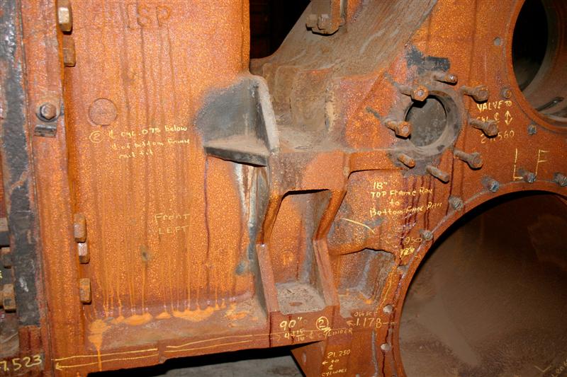 Photo: Bill Nash |
![]()
![]()